Volume Control in the Hi-Fi/High-End
© Alex Torres, Netanya
(part 1, 2004г., revised in 2007г.)
Preamble
This article was written 3 years ago, but only Part I was published.
Unfortunately - the time is always not enough :(, so the second and
the third parts were not finished. Maybe Its even better - during these
3 years some designs were changed, some new ideas were implemented
Now I have decided to finish this work and to change the structure
of this article. The 1st part was totally revised, all information concerning
the “nikitin” volume control was moved to the 2nd part, than now totally
dedicated to this design. The Part III (multi channel application for the
Home Theater) was moved to the Part IV and the new Part III will describe
the advanced tube/solid amplifier’s control (“nikitin” based).
The problems of the Volume control.
In spite of its simplicity, the volume control in the high level audio equipment still perform a problem. The “short pass” oriented audiophiles sometimes even not want any volume control - the music should sound “as
is”. But in reality - life without volume control is not comfortable.
What the volume control device must to do? The sound pressure level must linearly depend of the volume knob angle (in order to do this, the volume control element should be logarithmic). It is not hardly to make, if
you have only one channel, but in 2 channel stereo application (and multi channel Home theater applications too) the big problem is the equality of the channels controllers. Of course, volume controller is not
allowed to produce any noise (as acoustic, as electric). The good idea is to have the possibility of the remote control.
There are lot of solutions - “audiophile” ALPS potentiometers, simple or with the motor control ( by the way, why Alps? Bourns and Honywell make not worth potentiometers, but they are often more expansive due to an
aerospace orientation of these companies). Gold platted rotary switches, variable input transformers (well known “Sowter”, transformers from Alex Vorobiev, etc.) and even undeservedly contemned by audiophiles
electronic volume controllers. The last ones are very ambiguous - the wide range of the existing devices with the real high quality, to the low end devices, that are suitable only for portable mp3 players, car
audio, etc.
In this article I will try to observe some solutions - with electronic attenuators, with relays, with micro controller control, from the simple up to the more advanced.
Short review of the volume control IC.
Electronic volume control usually based on the voltage control amplifier - VCA (or VGA - Variable Gain Amplifier), for example at SSM2160, or switchable resistor network The most popular IC are digital potentiometers
(DS1802 from Dallas-Maxim, etc.), volume control chip CS3310 from Cirrus Logic (Crystal Semiconductors) compatible with PGA2310 from Burr-Brown (now - Texas Instruments), LM1972 from National Semiconductors.
One thing - many efforts to use 3-channel LM1973 fails. I’m sure that LM1972 and LM1973 have the same internal architecture, but the difference is very enormous.
Last time we have the new TI chips - PGA4311, than have 4 channels and better performance. (2 channel version - PGA2311). The old chip SSM2160 from Analog Devices provides 6 channel control, but worse
performance.
Various IC like LM1036 are out of out discussion due to their abominable sound. Certainly, this short review does not cover all volume control IC that exists all over the world. We will talk about some
representatives.
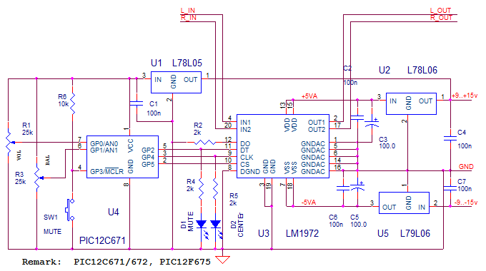
Simple LM1972 based volume Control.
LM1972 produce separate volume control of the 2 channels in the range from 0 to --78dB. Step is 0.5dB in the 0 - -48 dB range and 1dB at -48 - --78dB. This chip use simple 3-wire protocol (SPI bus):
If you need more then 2 channel control, you can use 2 solutions: it is possible to put some IC in parallel and to control all
channels simultaneously (for example - 2 parallel lm1972 are able to control LF, RF, LS, RS, Center and Sub, but you cannot
control all kinds of balance) Or - you can use daisy-chain connection. The first way is simpler, because you don’t need to make
any changes in the microcontroller’s software. Both two methods are shown at the diagram (right - parallel, left - daisy-chain) :
The most simple control device is shown at the diagram - is has no display, control provide by two potentiometers - not
logarithmic, not double way, not “audiophile quality”. Any most cheapest as you can find, even the value not need to be accurate
- use what you have, from 5k to 50k. This controller has also mute button and two LEDs to display mute status ant the balance control center position.
Maybe you have a question: “Why we need all this, to use potenciometer?”?”?”?” The answer is simple, and I give is above -this
potentiometers has no influence to the audio signal. Both volume and balance potentiometers change the voltage at
microcontroller’s ADC inputs. Micro measures the voltage and produce the necessary signals to the volume control chip. The
IC’s control line used also for LEDs, as thes lines can be in any position in inactive time.
For the best performance, it should be connected to big input resistance. If you amplifier have low - you should use the OP buffer
(ОРА2132, ОРА2134 и т.п.). Take care about ground wiring - IC has the special “digital” and “analog” ground pins.. Input signal can be up to 3V RMS. level. Input resistance - 40kOhm.
Remark: I received many complains than PIC12C671 is not widely available, and because using of the One Time
Programing micro is not a good idea for the D.I.Y, I make the software also for the flash micro - PIC12F675.
PGA2310 based Volume Control
Not all the people are able to make the changes in the software for LM1972, to work with PGA2310. Both chips have the same SPI interface, but different internal structure. This device is for those peoples.
At 1st, PGA2310 can not only attenuate the signal, but also to amplify! The control range is from -95.5 dB up to +31.5dB wit the
0.5 dB step. The powerful output can be loaded with 600 Ohm directly, without any buffers! But using of the full PGA’s range looks very plenty and I decided to make 3 software versions:
- Full – original control range, from -95.5 dB to +31.5 dB, but with 1dB step.
- NoGain – without amplification, i.e. from -63 dB to 0 dB, with 0.5 dB step
- Gain3 – with limited amplification, from -53 dB to +10dB with 0.5 dB step.
Balance control in all versions is +/-8 dB with 0.5 dB step.
With the “full version” the hardware limits are also possible (as will be described below).
As you can see - the schematic was not changed dramatically (power supplies regulators are not shown). The major differences
are in the software. Like LM1972 it is possible to use some PGA in parallel to obtain the multi channel volume control.
The possibility to operate with the low impedance (600 Ohm, 1000pF) load (output current of the PGA2310 – 35мА, and 2311
– 50мА) give us the elegant opportunity to use PGA as preamplifier, or to get other benefits as the buffer. Below you can see some examples of these solutions.
LM4780 (LM3886) inverting
Inverting schematic of the LM3886 (double version – LM4780) have better sound then widely used non-inverting. In order to
solve the stability problem, gain must be more than 10 (some people said even 20-30), and feedback resistor should be not
more then 50 kOhm. This determine the input resistor (input impedance) not more then 3-5 kOhm. With its low output
impedance, PGA2310/2311 can be buffers for inverting power amplifier. you must remember than input impedance of the PGA is also not very big - 10 kOhm, so sometimes PGA need the buffer at the input.
 |
There are no capacitor between the volume control and the power amplifier, and PGA’s output offset voltage will be amplified by
the LM. That’s why the output stage gain should be as small as possible. The same reason - to use PGA2311 instead of
PGA2310 due to it’s half offset. We not discuss LM3886/4780 in this article, you can pass to the data sheets and to the various
FAQs in the Internet. Bypass capacitors and Bushero output circuit are not shown at the diagram above.
SE Headphone Amplifier.
In opposite to the previous schematic, in this design more preferable is PGA2310, because the +/-5v power supply limitation of
the PGA2311. PGA2310 have up to +/-15v working range, with shown at the diagram below +/-12v power supply, PGA2310
with the emitter follower is able to provide output voltage 3.2v @ 32 Ohm load and 6.5v @ 300 Ohm, that is quite enough!
This design enjoys the “Full” control version with the hardware limit adjustment. With the help of two internal trimmers you can
limit the maximum and minimum volume, and to get the most comfortable control according to you headphones.
Remarks: p-n-p transistors MJE170 can be changed to BD140, etc., or mirroring the schematic and use n-p-n transistors like
MJE180, BD139, etc. The sound quality depends of the transistors - MJE170 from Motorola sound very nice, also BD140 from
Philips. But MJE170 from ST– sounds worse.. Transistors idle current is about 220 ma and can be adjusted by R1R2.
Remember - the efficiency of the “Class-A” amplifiers is like the efficiency of the steam train. All class-A amplifiers are
extremely HOT - be careful, use the heatsink. With 220 ma idle current, about 11W going to the heat on the two output
transistors and their resistors. If you will use only low impedance headphones (32 Ohm) - its better to drop the power supply
voltages from +/-12v down to +/-9v or even to +/-5v (using 7809/7909 and 7805/7905 regulators). If in opposite - you will use
only high impedance headphones (300, 600 Ohm) – it is practical to reduce idle current by increasing the emitter resistor.
-- end of part 1 --
|