Volume Control in the Hi-Fi/High-End
© Alex Torres, Netanya
(part 2, 2004, revised in 2007)
Cascade volume control from Alex Nikitin
Very nice design, published in the “Radio Hobby” magazine 2/2002, p 63 by Alex Nikitin (exCreekAudio) looks like radio frequency attenuator (and it was really based on it!) with relays. Has constant input impedance and easy control - you can use the wide range of the control as simple logic (binary counters), switches or microcontrollers. With or without level display.
Original schematic has 7 bit control (1-2-4-8-16-32-64 dB), with the control range 127dB with 1dB step. Usually , at the field, this is a little bit “overkill”, 6 bit (63dB) is quite enough. Many times I use
even 5 bit - the sane range (63dB) but with 2dB steps. To do this - simply delay the left step.
As shown above, this schematic have input impedance 10k, it is possible to recalculate all resistors to another value (I often use
20k equivalent). This volume control attenuator enjoy the highest level of sound, better then any popular “Alps” potentiometer. But, we should mention two things:
- Alex used Omron small signal relays with the gold plated contacts and 2 ms switching time. The quality of the device is totally depends of the relays quality!
- The precision smd resistors, were used to obtain the necessary resistance. Don’t try to select the value you need from the
regular 20% resistor with the precision digital multi meter! The precision (0.1-1%) resistors have not only accurate value,
but also are very stable in time and under the ambient temperature, have very small parasitic inductance and good noise level.
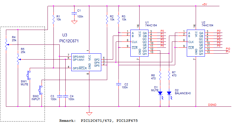
The control system below based on the same basis as the previous schematic, instead of LM1972 of PGA2310 two shift registers used in out first schematic:
Each shift register has 6 bit to the relays control, corresponding to the stereo channels. 2 bits of the lest register used for “mute” and “center” display, 2 bits of the right register - input channel control.
You can use various schematic to make the channel switch, for example like this 3 ch switch:
D3,D4,D5 LEDs– for the input channel display. R1,R2,R7 values– depends of the relays voltage. I built also another switches,
with the major difference in the LEDs decoding. On the schematic above the “11” code not used, on another - code “00” or “10”.
Take care of choosing the right compiled software or to make the corresponding defines (NoCh0 and NoCh2 options) if you want to compile the source code by yourself!
It will be not so difficult to compose other schematics, based on this example. The first thing - who need the balance control in
the High-End amplifier? As I know - nobody. If we will do this - we can use the relays with 2 ways, and we don’t need the
second shift register and relay’s transistors with their resistors. “Center” LED is also become unnecessary.. So, we moved
“mute” LED from the register’s output to the microcontroller’s pin, ad will use 6 register’s bits as the volume control and 2 bits as channel switching.
Think you are in a surprise condition now - how simple design we got! Flash microcontroller 12F675 has even his own
connector for the In-Circuit Programming. If you don’t want to use this feature - you are able to eliminate J1, C5, R5 (connect R4 to GP0 directly).
- end of the part 2--
|